
Run a pre-RFQ sheet metal DFM review that validates your flat pattern, checks bend geometry against K-factor and bend allowance calculations, confirms hole-to-bend spacing meets the 4T rule, and verifies gauge against mill standards before a single quote goes out. The deliverable you want: a priority-ranked PDF with annotated CAD callouts, flagging every issue by cost and schedule impact. For teams that want an independent set of eyes on their CAD model, Cad-dfm-check provides exactly that review, covering flat-pattern validation, K-factor checks, hole and bend spacing, ISO 2768 tolerance strategy, and a follow-up consultation.
A thorough pre-RFQ DFM review takes roughly 20–40 minutes per part for an experienced engineer. Skip it, and you risk significant delays and increased costs driven by tooling changes, rework, and process workarounds.
Table of Contents
- What does a sheet metal DFM review actually check?
- How do forming and cutting processes change the DFM rules?
- Engineer's quick sheet metal DFM checklist before sending an RFQ
- How to prepare CAD files for an effective DFM review
- What do professional DFM reviews cost and how fast do they turn around?
- Common late-stage failures and the hidden cost of skipping DFM
- How engineering teams should act on a DFM report
- Key Takeaways
- The checks most engineers learn too late
- Cad-dfm-check sheet metal DFM reviews: what you get and how to start
- Useful sources and further reading
What does a sheet metal DFM review actually check?
A professional sheet metal DFM review works through the part from blank to assembly. The core checks:
- Material and gauge: Confirm the specified alloy and thickness match a standard mill gauge. Non-standard thickness triggers custom stock orders and cost spikes.
- Flat pattern and nestability: Export and validate the flat layout for distortion, interference, and material utilization. Holes near bend lines deform during forming if the flat pattern is never checked.
- Bend radii and K-factor: Verify inside bend radii meet material-dependent minimums (mild steel: ~1t; 5052 aluminum: ~1t–1.5t; stainless 304: ~1.5t–2t). K-factor for bend allowance typically runs 0.30–0.40 for mild steel and 0.33–0.50 for aluminum.
- Hole-to-bend and feature-to-bend distances: The 4T rule is the conservative baseline. Keep all holes and features at least four times the material thickness from any bend line to prevent distortion.
- Minimum flange length: Flanges shorter than roughly 4× material thickness are difficult to hold in a press brake and produce inconsistent angles.
- Hole and slot minimums: Hole diameter should be no smaller than material thickness for punching. Slot width must be at least equal to material thickness.
- Bend relief: Missing relief at intersecting bends causes tearing. Add rectangular or circular relief cuts with a minimum width of 0.5t and depth of t plus bend radius.
- Tolerance strategy: Apply ISO 2768 general tolerances for non-critical features. Tighten only where assembly or function demands it. Rationalizing tolerances to standard levels can reduce fabrication cost by 15–30%.
- Design-for-assembly: Self-locating features, PEM inserts, and rivets reduce assembly time compared to welding in most sheet-metal assemblies. See the DFM vs. DFA breakdown for when each approach applies.
Some checks are purely CAD-based (flat-pattern export, feature locations). Others require process context.
Pro Tip: The three checks that find the biggest cost risks fastest: bend radii below material minimums, holes violating the 4T rule, and non-standard gauge choices. Start there.
How do forming and cutting processes change the DFM rules?
Design rules are not universal. The process determines what geometry is acceptable.
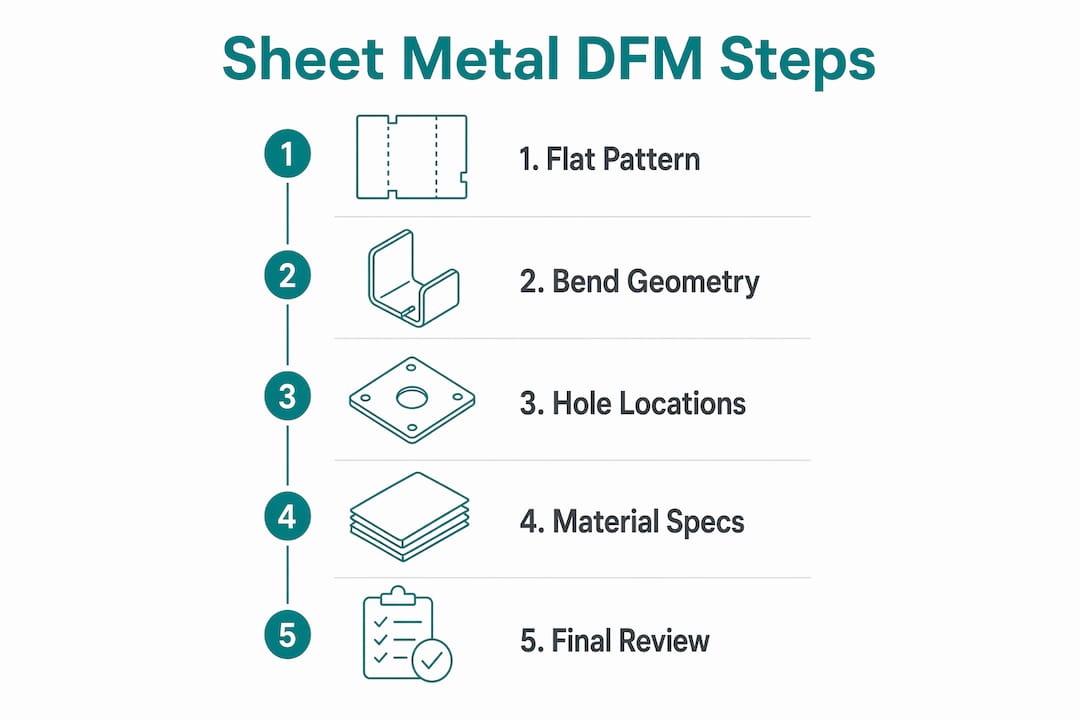
Press brake forming
Press brake work lives and dies on bend allowance accuracy. K-factor validation matters most here because each bend compounds stack-up error across a multi-bend part. Minimum flange length is critical: a flange too short to seat in the die produces inconsistent angles across a production run. Bend relief prevents tearing at corners where two bends intersect close to an edge.

Stamping and high-volume forming
Stamping uses hard tooling, so geometry that seems fine for a one-off press brake part can be problematic at volume. Hole and slot geometry must account for punch-to-die clearance. Embossed or coined features have tighter depth limits than press brake equivalents. The repeatability advantage of stamping comes with a tooling investment that makes late-stage design changes expensive.
Laser cutting and waterjet
Laser cutting gives you tight cut-edge tolerances and the freedom to place holes close to edges without punching constraints. A hole smaller than material thickness that would fail in punching is often fine for laser. The tradeoff: laser-cut parts still go to a press brake for forming, so the same bend-line rules apply downstream. A tiny hole placed 1.5t from a bend line might cut cleanly but will distort the moment the part hits the brake. Waterjet adds a slightly rougher edge and slower cycle time, which affects cost at volume but not the forming rules.
Engineer's quick sheet metal DFM checklist before sending an RFQ
Run these checks at the CAD station before the files leave your desk.
- Export the flat pattern from your CAD model and visually inspect it for distortion, overlapping geometry, and missing bend relief.
- Verify material gauge against standard mill sizes. For steel, common gauges run 26 ga (0.018″) through 10 ga (0.134″). For 5052 aluminum, confirm the temper (H32 is the most common fabrication choice).
- Check all bend radii against material minimums. Mild steel: 1t minimum. 5052-H32 aluminum: 1t–1.5t. Stainless 304: 1.5t–2t. Never design below 1t without material-specific testing.
- Apply the 4T rule to every hole, slot, and cutout. Feature-to-bend distance must be ≥ 4× material thickness. For holes over 25 mm in diameter, increase that clearance to 2.5× thickness plus bend radius.
- Confirm flange lengths are ≥ 4× material thickness. Short flanges are a press brake liability.
- Check hole and slot minimums: hole diameter ≥ material thickness; slot width ≥ material thickness; slot length ≤ 5× slot width.
- Add bend relief at every intersecting bend. Minimum width: 0.5t. Minimum depth: t + bend radius + 0.02″.
- Set tolerances using ISO 2768 for general features. Call out critical dimensions explicitly with GD&T datums where assembly fit depends on them.
- Confirm uniform material thickness throughout the part. Variable thickness implies welding or a multi-part assembly, which adds cost and complexity.
Pro Tip: Run a quick bend-sequence review after the flat-pattern check. A bend order that seems logical in 3D can create tooling interference in the actual press brake sequence.
How to prepare CAD files for an effective DFM review
Send a reviewer everything they need to give you a complete answer, not just the 3D model.
File package to include:
- Native CAD file (SOLIDWORKS, CATIA, Creo, or equivalent) plus a STEP or IGES neutral export
- Flattened DXF or flat-pattern export
- 2D drawing with title block, revision, and GD&T callouts
- BOM or part spec listing material alloy, temper, and finish
Documentation checklist:
- Material: alloy, temper, and coating or finish (e.g., 5052-H32, clear anodize)
- Target quantity and expected production runs (prototype vs. 10,000/year changes the process recommendation)
- Target unit cost or cost goal
- Critical dimensions and tolerances beyond ISO 2768
- Assembly constraints: mating parts, fastener types, orientation
- Process preference if known (press brake, stamping, laser)
Label critical features directly on the drawing. Include expected assembly orientation and a target schedule. A reviewer who knows your timeline can flag which issues are must-fix before tooling versus acceptable for a pilot run. Autodesk Fusion's nesting and 2D layout exports can help prepare flat patterns and optimize material utilization before submission.
What do professional DFM reviews cost and how fast do they turn around?
Independent sheet metal DFM reviews are typically priced per part on a fixed-fee basis. Single-part quick reviews for standard press brake geometry generally turn around in 24–72 hours. Multi-part assemblies or parts requiring DFA analysis and follow-up consultation run 1–2 weeks depending on complexity.
Add-ons that affect scope and price: DFA review (assembly sequence, self-locating features, fastener strategy), Moldflow or forming simulation for complex geometry, and priority handling for compressed schedules.
| Deliverable | What it contains |
|---|---|
| Priority-ranked PDF report | Full issue list ranked by cost and schedule impact, with recommended fixes |
| Annotated CAD screenshots | 3D and flat-pattern markups showing exact problem locations |
| Suggested CAD edits | Replacement geometries or dimension changes for each flagged issue |
| Cost-impact notes | Rough cost or schedule consequence for each issue if left unresolved |
| Follow-up consultation | Live call to walk through the report and answer process questions |
Pricing models vary. Per-part fixed pricing is the most common for independent reviews and gives engineering teams a predictable cost before committing to tooling.
Common late-stage failures and the hidden cost of skipping DFM
The most expensive sheet metal problems are the ones that reach the shop floor. Misplaced holes that violate the 4T rule look fine in a 3D view but deform into ovals during forming, making threaded inserts impossible to install correctly. A non-standard gauge choice that slips through review forces a custom stock order, adding lead time before a single part is bent. Missing self-locating features mean assembly fixtures must compensate, adding labor cost per unit across the entire production run.
Designs that skip DFM checks can average 6.2 extra weeks and a ~35% cost premium. Tooling changes after a die is cut are the worst-case scenario. A press brake tool modification to accommodate a radius change that should have been caught in CAD can cost thousands of dollars and delay production by weeks. The same fix in CAD before RFQ takes minutes. Tooling changes after a die is cut are the worst-case scenario. A press brake tool modification to accommodate a radius change that should have been caught in CAD can cost thousands of dollars and delay production by weeks. The same fix in CAD before RFQ takes minutes.
The pattern repeats across processes. For a broader look at how CAD errors compound into tooling delays, the injection molding equivalent follows the same logic: problems caught in CAD cost almost nothing; problems caught after tooling cost multiples of the original project budget.
Budget for a pilot or first-article run when changes are unavoidable after tooling. Catching a forming issue on part one of a pilot run is far cheaper than discovering it at full production volume.
How engineering teams should act on a DFM report
A good report is only useful if the team acts on it systematically.
Triage first. Sort issues into three buckets: safety or functional failures that block production, high-cost items (tooling changes, rework), and low-cost cosmetic items that can be deferred. Fix the first bucket before anything else.
Assign ownership. Each flagged issue needs a named engineer responsible for the CAD update and a deadline. Unassigned issues drift.
Estimate cost and time per fix. Some changes take five minutes in CAD. Others require a design review with the supplier. Know which is which before you commit to a schedule.
Update CAD and flat pattern together. A geometry change that is not reflected in the flat pattern creates a new class of errors. Always regenerate and re-export after each revision.
Share the annotated CAD with your supplier. The reviewer's markups give the supplier context for why a feature changed. Ask for the supplier's process constraints and document agreed assumptions in the RFQ. That conversation often surfaces additional constraints the reviewer could not anticipate without knowing the supplier's specific tooling inventory.
When schedule is compressed, defer cosmetic and low-cost items to a revision cycle after the pilot run. Never defer a bend radius below material minimum or a hole that violates the 4T rule. Those two categories cause the most production failures.
Key Takeaways
A pre-RFQ sheet metal DFM review that catches bend radii, hole spacing, and tolerance errors in CAD prevents the tooling changes and rework that average 6.2 extra weeks and a ~35% cost premium.
| Point | Details |
|---|---|
| Run the review before RFQ | Catching issues in CAD costs minutes; the same fix after tooling costs thousands and weeks. |
| Prioritize bend and hole checks | Bend radii below material minimums and holes violating the 4T rule cause the most production failures. |
| Rationalize tolerances | Applying ISO 2768 to non-critical features can reduce fabrication cost by 15–30%. |
| Send complete documentation | Include native CAD, flat-pattern DXF, 2D drawing, material spec, target quantity, and critical dimensions. |
| Cad-dfm-check delivers the full package | Per-part fixed-price reviews with a priority-ranked PDF, annotated CAD screenshots, and a follow-up consultation. |
The checks most engineers learn too late
Sheet metal DFM is one of those topics that academic programs rarely cover in depth. Most engineers learn it on the job, usually after a tooling change or a rework cycle that stings the project budget. What I see repeatedly in submitted CAD files: bend radii set to a round number that looks clean in the model but sits below the material minimum, holes placed by eye that happen to land just inside the 4T boundary, and tolerances copied from a machined-part drawing applied wholesale to formed features.
The priority-ranked PDF format matters because not every issue deserves equal urgency. A cosmetic edge condition and a hole that will deform during forming are not the same problem, and treating them as equal wastes the team's revision time. Annotated CAD screenshots give the engineer the exact location and the exact fix, not a written description they have to interpret. The follow-up consultation closes the loop on process questions the report cannot fully answer in writing.
The single most consistent win: catching a non-standard gauge choice before the RFQ goes out. Suppliers quote against standard stock. A non-standard thickness triggers a custom order, a longer lead time, and a higher unit cost, none of which show up in the original budget. That one check, run in under a minute, pays for the review.
Cad-dfm-check sheet metal DFM reviews: what you get and how to start
If your team needs an independent manufacturability review before committing CAD files to tooling or quoting, Cad-dfm-check offers per-part fixed-price reviews with a stated turnaround so you know the timeline before you submit.
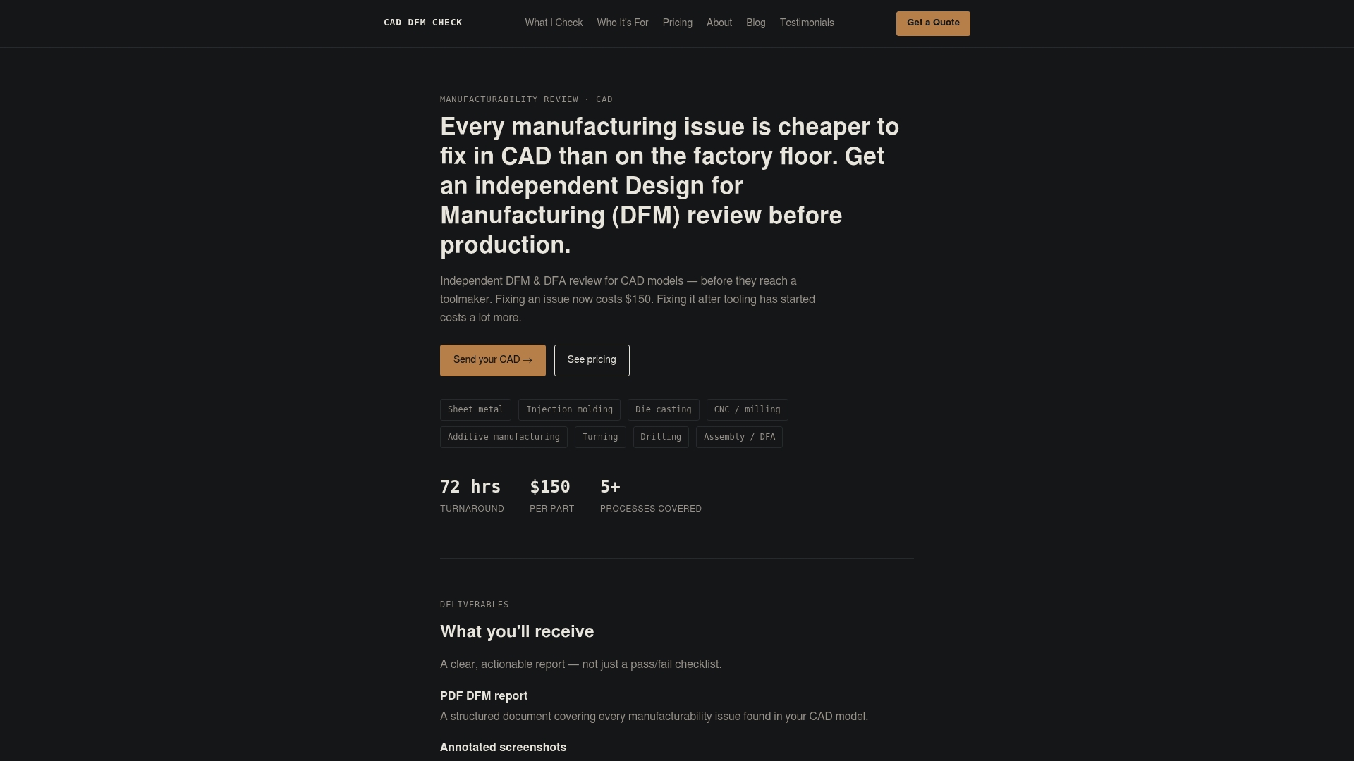
Every sheet metal review includes a priority-ranked PDF report with cost and schedule impact per issue, annotated CAD screenshots marking exact problem locations, suggested CAD edits with replacement geometries, and a follow-up consultation to walk through the findings. Add-ons include DFA review for assembly sequence and fastener strategy, and priority handling for compressed schedules.
- Priority-ranked PDF with issue list and recommended fixes
- Annotated 3D and flat-pattern screenshots
- Suggested CAD edits and replacement geometries
- Cost-impact notes per issue
- Follow-up consultation included
Pro Tip: Submit your flat-pattern DXF alongside the native CAD file. Reviewers who can see both the folded geometry and the flat layout flag issues faster and give more specific fix recommendations.
Request a review or see what past clients say about the process on the testimonials page. Full service details are at cad-dfm-check.com.
Useful sources and further reading
- Sheet Metal DFM Design Guidelines for Formed and Punched Parts — Five Flute's first-principles guide covering blank cutting, press brake, stamping, and assembly considerations; useful for validating process-specific design rules.
- Sheet Metal DFM Checklist: 17 Things to Check Before Requesting a Quote — DRAmetal's pre-RFQ checklist with time estimates and cost-impact data; good for benchmarking your internal review process.
- Avoiding Sheet Metal DFM Issues — Protolabs' guide on flat-pattern validation, bend relief, and hole placement relative to bend lines.
- 8 Mistakes to Avoid When Designing Sheet Metal Parts — Protolabs' practical list covering the 4T rule, consistent gauge, and common press brake errors.
- Best Practices for Designing Custom Sheet Metal Parts — Fabcon's guide with material-specific bend radius tables, K-factor ranges, and tolerance rationalization data.
- Design for Manufacturing Software, Autodesk Fusion — Overview of DFM/DFMA automation features in Fusion, including nesting, flat-pattern exports, and simulation; useful for understanding where software checks end and human review begins.