TL;DR:
- Building constraints into CAD models prevents assembly errors before manufacturing begins. Implement asymmetric features, connector keying, and parametric rule checks to control orientation and sequence errors. Conduct early design reviews to identify and fix poka yoke gaps, reducing costly rework and ensuring high-quality production.
Poka yoke design for CAD means building physical and digital constraints directly into your model so assembly errors become structurally impossible before a single tool is cut. Start with these three moves: add an asymmetric boss or offset hole to eliminate any chance of reversed assembly, key every connector and dowel pin so orientation is enforced by geometry, and embed parametric rule checks or model-based annotations that flag wall thickness or draft violations inside your CAD environment. Do those three things before your next design review and you've already closed the most common failure modes.
Pro Tip: Apply the "photographability" test to every error-proofing change: if you can't take a picture of it and show that the wrong assembly is physically blocked, you have a policy, not a poka yoke.
- Add an asymmetric feature (offset boss, D-flat, non-uniform bolt pattern) to every part that could be installed backward.
- Key or notch every connector, cable, and fluid fitting so mating is direction-specific.
- Embed CAD rule checks (wall thickness, draft angle, undercut flags) as parametric constraints, not post-review notes.
- Standardize fastener diameters per assembly zone so a wrong-length bolt simply won't fit.
Table of Contents
- Why poka yoke design matters before you commit to tooling
- The three core techniques and how to apply them in CAD
- Your pre-tooling CAD checklist, organized by process
- How to validate poka yoke features before tooling
- What an independent DFM review finds that your team misses
- Timeline, who to involve, and the cost trade-off
- Key Takeaways
- The mistake most teams make with error-proofing
- What a Cad-dfm-check review delivers for your next CAD model
- Useful sources
- FAQ
Why poka yoke design matters before you commit to tooling
Shigeo Shingo built the poka yoke concept into the Toyota Production System on a single premise: prevention is categorically better than detection. Detection catches an error after it occurs; prevention makes the error structurally impossible. Most engineering teams default to inspection checklists and audits, which is exactly backwards. Catching a reversed housing at final QC costs orders of magnitude more than designing the housing so it can only seat one way.
ASQ frames this as two distinct functions: control functions that stop the process from proceeding when a condition is wrong, and warning functions that alert an operator. Control functions are far stronger for CAD-to-tooling workflows because they remove the human decision entirely. A warning assumes someone is paying attention; a control function doesn't need them to be.
"The question is not 'why did this person make this mistake?' The question is 'what about the design of this process allowed the mistake to be possible?'" — Kainexus Poka-Yoke Primer
In regulated industries, this distinction has teeth. IATF 16949 and AS9100 both expect documented poka yoke evidence for high-volume production and PPAP submissions. FDA guidance for medical devices similarly requires risk-based design controls that demonstrate error prevention, not just detection. If your product touches automotive, aerospace, or medical supply chains, poka yoke documentation isn't optional.
Manufacturing risks that early CAD error-proofing eliminates:
- Reversed or mis-oriented parts reaching assembly
- Mixed fastener lengths causing under-torque or thread strip
- Wrong-handed components assembled into mirror-image positions
- Incorrect sub-assembly sequence leading to trapped components
- Tooling built to a symmetric feature that should have been asymmetric
Pro Tip: Run a quick FMEA before your next CAD review. Rank failure modes by severity and occurrence, then target the top three with physical poka yoke features first.
The three core techniques and how to apply them in CAD
Physical poka yoke methods fall into three categories, each with direct CAD implementations.

Contact method
The part's geometry physically prevents incorrect mating. In CAD, this means asymmetric bosses, D-flats on shafts, offset dowel pins, or non-uniform bolt-circle patterns. A connector housing with one pin shifted 5 mm off-center cannot be plugged in backward. Two dowel pins of different diameters (say, 6 mm and 8 mm) make incorrect fixture loading impossible without forcing. These are low-cost, high-reliability fixes that require no sensors, no power, and no calibration.
Motion-step method
A fixture or assembly jig enforces the correct sequence of operations. In CAD, design the fixture so Step 2 is physically inaccessible until Step 1 is complete. A cover plate that can't be bolted down until a sub-assembly is seated, or a clamp that won't close until a locating pin is engaged, are both motion-step controls built into the geometry.
Fixed-value method
A specific count or quantity is enforced by design. Kitting trays with exactly the right number of cavities, torque-driver interlocks that won't release until a preset value is reached, or a PCB with a unique connector count that prevents partial population are all fixed-value controls. In CAD, you can model the kit tray geometry and specify the torque driver interlock as a design requirement tied to the BOM.
Software-driven poka yoke in CAD:
- Parametric constraints that flag violations of minimum wall thickness or draft angle in real time
- Assembly mates that only allow one valid orientation (CAD-level contact method)
- BOM checks that cross-reference fastener specs against hole diameters
- Digital work instructions with barcode or QR triggers that prevent sequence skipping on the shop floor
Pro Tip: Shifting one hole 5–10 mm off-center or using two different dowel diameters costs almost nothing in CAD and eliminates an entire class of orientation errors. Do this before you add any sensor.
"The best solutions are low-cost, low-tech, and highly effective — and they tend to speed up the process rather than slow it down." — Kainexus Poka-Yoke Primer
Your pre-tooling CAD checklist, organized by process
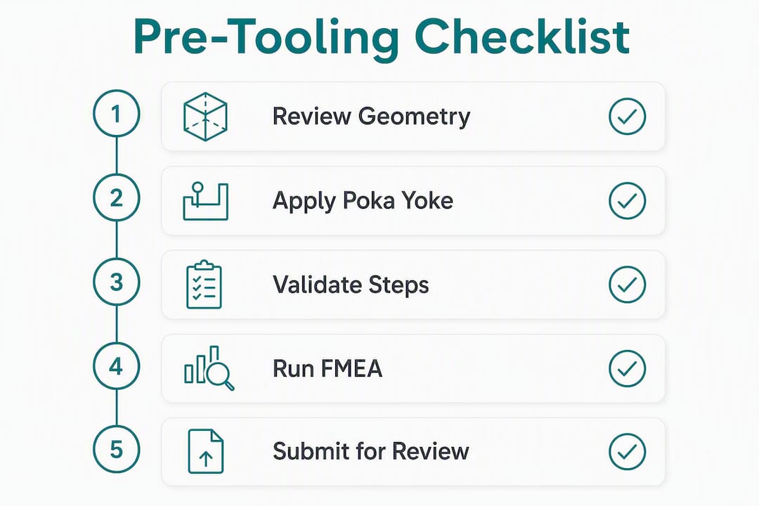
Run this before sending any CAD file to a tooling vendor or for quoting.
| Process | Check | Common failure mode | Quick CAD fix |
|---|---|---|---|
| All | Asymmetric feature present | Reversed assembly | Offset one boss or hole 5–10 mm |
| All | Fastener standardization | Mixed bolt lengths | Limit to one diameter per zone |
| Injection molding | Draft angle ≥ 1° on all walls | Part sticks in tool | Add draft in CAD; check with Moldflow simulation |
| Injection molding | Uniform wall thickness | Sink marks, warpage | Redesign thick sections with coring |
| Sheet metal | Bend relief at all corners | Tearing at bend | Add relief slots in flat pattern |
| CNC | Fixturing faces and clamp clearances | Chatter, mis-location | Add datum faces; check clamp access |
| Assembly | Torque access clearance | Under-torqued fasteners | Verify socket clearance in assembly model |
General CAD checks (apply to every process):
- Every symmetric part has at least one asymmetric feature or label that survives the manufacturing process
- All connectors, cables, and fluid fittings are keyed or polarized in the CAD model
- Undercuts are flagged and either redesigned or documented as requiring side-action tooling
- Wall thickness is within the process window (typically 1.5–4 mm for injection molding)
- Blends and fillets are sized to the tooling radius, not left as sharp corners
Pro Tip: Check your assembly model in the "wrong" orientation first. If the CAD mates still close, your poka yoke feature isn't strong enough.
How to validate poka yoke features before tooling
Validation follows a sequence from digital to physical.
- CAD rule check. Run parametric constraint checks and interference detection in your CAD tool. Confirm that the asymmetric feature prevents the incorrect mate.
- Parametric tolerance stack. Analyze whether the poka yoke feature holds across the full tolerance range. A 5 mm offset boss that shrinks to 3.8 mm at minimum material condition may not be enough.
- Virtual assembly simulation. Assemble the model in both correct and incorrect orientations. The incorrect orientation should produce a visible clash or an unsatisfied mate.
- Moldflow or FEA check. For injection-molded parts, run a Moldflow simulation to confirm that asymmetric features don't create fill imbalances or stress concentrations.
- Rapid prototype proof. Print or CNC a soft prototype and physically try to assemble it wrong. Cardboard try-storming works for early-stage fixtures. The wrong assembly should be obviously blocked.
- Shop-floor verification. Run a deliberate "bad part" through the fixture or sensor system once per shift to confirm detection is still active. Sensors that aren't verified regularly create false confidence.
KPIs to track poka yoke effectiveness:
- First-pass yield at assembly (target: improvement after each poka yoke change)
- Assembly time per unit (poka yoke features should reduce, not increase, cycle time)
- Torque-error rate per shift
- Number of tooling change orders attributed to orientation or assembly errors
"A sensor that hasn't been calibrated in six months provides false confidence rather than quality." — Kainexus Poka-Yoke Primer
Pro Tip: Set a baseline KPI measurement before implementing any poka yoke change. Without a before/after comparison, you can't quantify the ROI or justify the next round of fixes.
What an independent DFM review finds that your team misses
Design teams are too close to their own models. An independent DFM review brings a manufacturing engineer's eye to your CAD files before tooling is ordered.
What a reviewer checks for:
- Symmetric features that should be asymmetric (orientation risk)
- Fastener mismatches between BOM and hole specs
- Missing draft, insufficient wall thickness, or undercuts that require expensive side-action tooling
- Assembly sequences that allow incorrect sub-assembly without a physical stop
Sample report items from a Cad-dfm-check review:
| Severity | Issue | Recommended CAD change |
|---|---|---|
| Critical | Housing is fully symmetric; can be assembled reversed | Add 6 mm offset boss on one face |
| Major | Three fastener diameters used in one assembly zone | Standardize to M4 throughout |
| Minor | Fillet radius smaller than tool radius on CNC pocket | Increase fillet to 3 mm |
What to submit for the best review result:
- Native CAD files (STEP or native format) plus PDF drawings
- BOM with fastener specs and target materials
- Assembly instructions or sequence diagram
- Target manufacturing process and annual volume
- Acceptance criteria or critical dimensions
"Designers commonly confuse inattentive operators with bad design. A DFM review catches the symmetric features and missing orientation constraints that a design team stops seeing after the tenth revision." — Whole-Spec, Poka-Yoke Design Tips
See client outcomes for examples of how independent reviews have reduced rework and eliminated tooling change orders.
Timeline, who to involve, and the cost trade-off
Implementation timeline:
- Hours: Offset a boss, add a D-flat, standardize fasteners. Any CAD modeler can execute these with no tooling impact.
- Days: Redesign a symmetric housing, add fixture locating features, update the BOM and assembly instructions. Involves the design lead and manufacturing engineer.
- Weeks: Tooling-impacting redesigns (adding a side-action feature, changing a parting line). Requires tooling vendor sign-off and may affect lead time.
Who to involve at each stage:
- CAD modeler: executes quick fixes (hours-level changes)
- Design lead: approves medium-effort changes and updates the design intent
- Manufacturing engineer: validates fixture and process compatibility
- Tooling vendor: reviews any change that affects the tool steel or parting line
- QA engineer: sets acceptance criteria and KPI baselines
- Independent DFM reviewer: ideally engaged before the design freeze, not after
A single tooling change order in injection molding typically runs $2,000–$15,000 and adds 4–8 weeks to the schedule. A CAD-level poka yoke fix costs hours of engineering time. Schedule your DFM review at the 60–70% design completion mark, when changes are still cheap and the geometry is stable enough to review meaningfully.
Key Takeaways
Prevention-first poka yoke design, applied directly in CAD before tooling, is the single most cost-effective quality intervention available to engineering teams.
| Point | Details |
|---|---|
| Prevention beats detection | Control functions that block incorrect assembly are stronger than warning alerts that rely on operator response. |
| Three core CAD techniques | Contact (asymmetric geometry), motion-step (sequence-enforcing fixtures), and fixed-value (count/torque interlocks) cover most assembly error modes. |
| Validate digitally and physically | Run parametric checks, virtual assembly, and a rapid prototype proof before committing any file to tooling. |
| DFM review timing matters | Engage an independent reviewer at 60–70% design completion to catch poka yoke gaps while changes are still inexpensive. |
| Cad-dfm-check finds ranked opportunities | A Cad-dfm-check review delivers a priority-ranked PDF with annotated screenshots and specific CAD changes, covering injection molding, sheet metal, CNC, and assembly. |
The mistake most teams make with error-proofing
The most common pattern in DFM reviews is a design that is technically complete but physically ambiguous. The part looks right in CAD, the BOM is correct, and the assembly instructions are clear. Then the first batch comes back with a significant portion of housings installed backward, and the team's first instinct is to add a label or retrain the assembler.
That instinct is wrong, and Shingo said so explicitly. The error-proofing principle isn't that workers need better instructions. It's that the design allowed the error to be possible in the first place. A label is a warning function at best. A geometric constraint is a control function. One of those can be ignored under fatigue or time pressure; the other cannot.
Low-cost physical constraints consistently outperform complex sensor systems for early-stage products. A sensor needs calibration, verification, and standard work to confirm it's still functioning. An offset boss needs nothing after it's machined. For teams building their first production run, that difference in maintenance burden is significant.
The collaborative piece matters too. The best poka yoke features come from a conversation between the CAD modeler and the person who will actually run the assembly line. That conversation rarely happens without a structured review forcing it. Build the DFM review into your milestone schedule, not as a final gate, but as a mid-design checkpoint where manufacturing can push back before the geometry is frozen.
What a Cad-dfm-check review delivers for your next CAD model
Before your CAD files go to a tooling vendor, a Cad-dfm-check independent DFM review gives your team a ranked list of poka yoke gaps and manufacturability risks, with specific CAD changes attached to each finding.
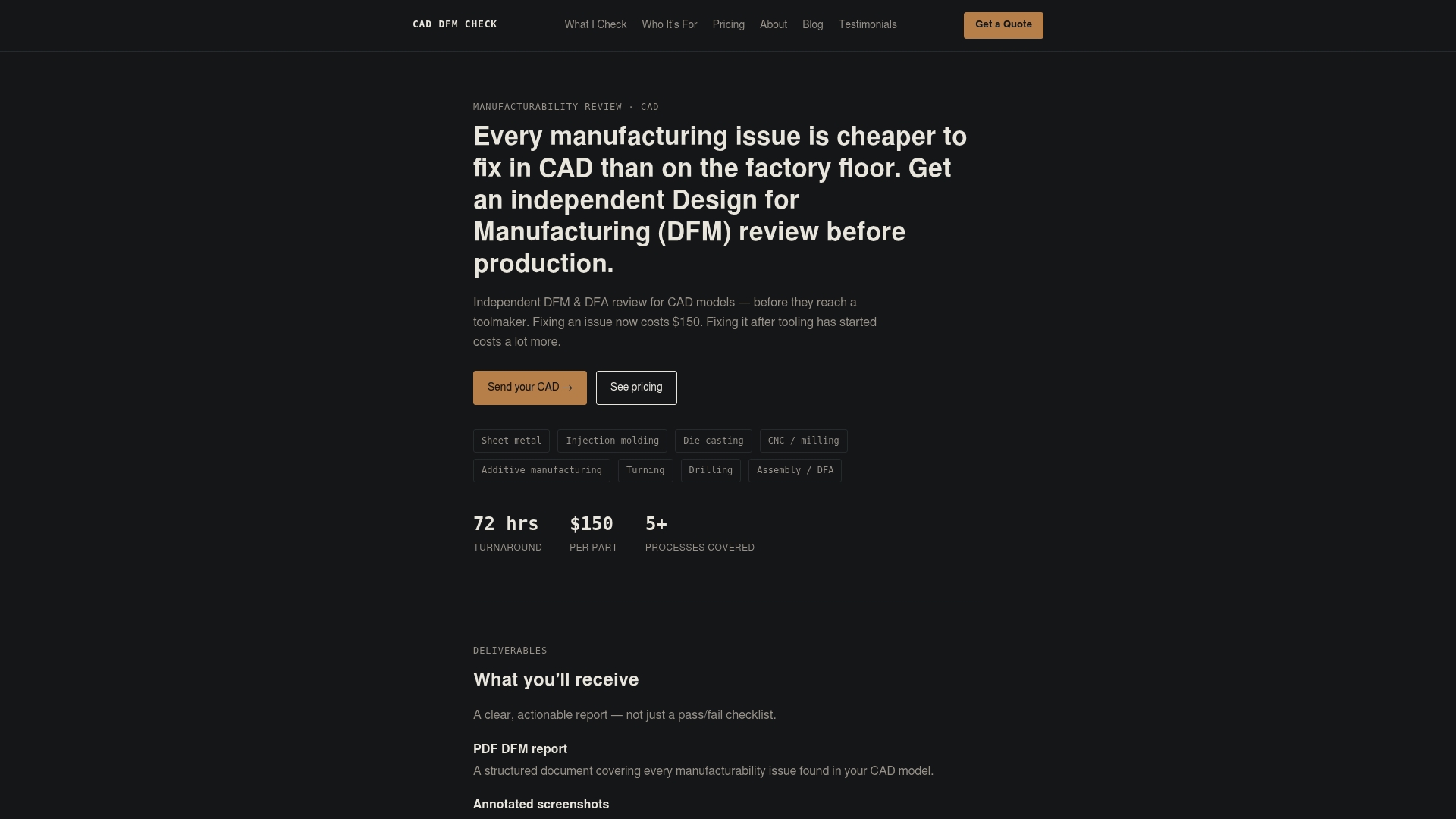
Submit your native CAD files, BOM, target process, and assembly sequence, and you receive a priority-ranked PDF report with annotated screenshots, severity ratings (critical, major, minor), and recommended geometry changes. For injection-molded parts, Moldflow simulation results are included. The report covers orientation risks, fastener mismatches, draft and wall thickness issues, and tooling-impacting features, all ranked so your team knows what to fix first.
The ROI is straightforward: a review engagement costs a fraction of a single tooling change order, and it happens before any steel is cut. Request a quote to get your CAD model reviewed before your next design freeze.
Useful sources
- Error Proofing | ASQ — Authoritative definition of control vs. warning functions; the standard reference for poka yoke in quality management.
- Poka-yoke — Lean Enterprise Institute — LEI's lexicon entry defining shutdown controls vs. warning alerts and the criteria for good poka yoke devices (simple, reliable, inexpensive).
- Error Proofing Training — ASQ — Codifies the stepwise error-proofing process used in both office and manufacturing contexts; useful for teams building a formal program.
- Mistake-Proofing in Manufacturing — Tulip — Covers physical and digital poka yoke techniques including digital work instructions, barcode readers, and sensor-driven interlocks.
- Poka-Yoke Primer — Kainexus — Practitioner-level guide covering prevention vs. detection, the photographability heuristic, and try-storming for rapid prototyping.
- Poka-Yoke Design Tips — Whole-Spec — Design-focused guidance on asymmetric features, keying, and the link between poka yoke and IATF 16949 / AS9100 requirements.
- CAD DFM Check Blog — Practical tutorials on DFM and DFA practices, including injection molding CAD mistakes and how DFM/DFA complement poka yoke design.
FAQ
What is poka yoke design in manufacturing?
Poka yoke design means building physical or digital constraints into a product or process so that errors are structurally prevented rather than caught after the fact. ASQ defines two mechanisms: control functions that stop incorrect progression, and warning functions that alert operators.
How do you add poka yoke features to a CAD model?
Offset one boss or hole 5–10 mm from center, use two different dowel diameters, add a D-flat to any shaft that must be oriented, and embed parametric rule checks for draft angle and wall thickness. These contact-method changes cost hours of CAD time and eliminate the most common orientation errors.
When should you schedule a DFM review for poka yoke?
At 60–70% design completion, when the geometry is stable enough to review but changes are still inexpensive. A review at this stage catches orientation risks and fastener mismatches before tooling is ordered.
Does poka yoke apply to regulated industries like automotive or medical?
Yes. IATF 16949 and AS9100 both expect documented poka yoke evidence for high-volume production and PPAP submissions. FDA design controls for medical devices similarly require risk-based prevention measures, not just inspection.
What KPIs measure poka yoke effectiveness?
Track first-pass yield at assembly, assembly time per unit, and torque-error rate per shift. Set a baseline before implementing any change so you can quantify the improvement and justify further investment.