
Injection molding DFM is the discipline of reviewing a CAD model against real tooling and process constraints before a single line of steel gets cut. Your three immediate actions: check that nominal wall thickness is consistent throughout the part, establish your parting line and draft orientation, and map out your gating and ejection plan. Do those three things before anything else.
Quick-start checklist (apply in your next CAD session):
- Confirm nominal wall thickness falls within the typical 1.5 mm nominal value used in injection molding for ABS and PP, and that no section has abrupt thickness transitions greater than 2:1 ratio.
- Add minimum 1° draft to all surfaces parallel to mold opening; bump to 3°–5° for textured surfaces
- Identify the parting line and mark cosmetic vs. functional surfaces in your model
- Position the gate at the thickest section to promote flow toward thinner walls
- Flag any undercuts that will require slides or lifters so tooling cost can be estimated early
Pro Tip: Before you request tooling, lock your nominal wall, parting line, and gate location into the CAD model as named annotations or design notes. Changing any of these after the tool is cut is expensive. Everything else is adjustable; those three are not.
For parts with thin walls, long flow lengths, or tight cosmetic requirements, geometric DFM rules alone are not enough. Autodesk Moldflow or ANSYS Moldflow simulation should be part of the review to predict weld lines, air traps, and warpage before sampling.

Table of Contents
- What is an injection molding DFM report, and when do you need one?
- The core DFM checklist: numeric rules and immediate CAD fixes
- How to handle undercuts, slides, and multi-cavity decisions
- When does Moldflow add value that geometric DFM cannot?
- Common defects and the exact design fixes that prevent them
- How to package your CAD files for a fast, useful DFM review
- How a Cad-dfm-check review works and what you receive
- Key Takeaways
- What most DFM reviews actually reveal
- Get a fixed-price DFM review for your injection molded part
- Useful sources for deeper reading
What is an injection molding DFM report, and when do you need one?
A DFM report is a structured evaluation of your 3D model against injection-molding constraints, delivered before tooling begins. It visualizes findings with annotated screenshots, color-coded wall maps, and prioritized fix lists covering gate placement, draft angles, ejector locations, and undercut risks. Think of it as a pre-tooling audit that tells you exactly what to change—and in what order.
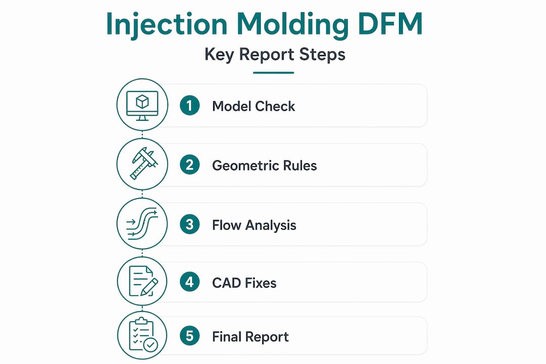
A complete report typically includes wall-thickness analysis, draft verification, gate and parting-line proposals, undercut assessment, and, when the geometry warrants it, a mold flow simulation result. The output is a priority-ranked PDF with annotated CAD screenshots and specific change recommendations, not a generic checklist.
When to request one:
- At concept freeze, before detailed tooling design begins
- Before committing to a multi-cavity tool, where per-cavity errors multiply cost
- Any time a supplier quotes without providing written DFM feedback
The table below clarifies which level of review fits which situation.
| Review type | Who needs it | Typical lead time | Effort/cost band |
|---|---|---|---|
| Quick geometric DFM | Simple parts, conservative geometry, low volumes | Hours to 1 day | Low |
| Full DFM report | Complex geometry, tight tolerances, cosmetic surfaces | 1–3 business days | Moderate |
| Moldflow (MFA) simulation | Thin walls, long flow paths, warpage-critical parts | 2–5 business days | Moderate–high |
Applying DFM only after tooling problems appear is the most common and most expensive failure mode in injection molding programs. The earlier the review, the cheaper the fix.
The core DFM checklist: numeric rules and immediate CAD fixes
Uniform wall thickness is the single most impactful DFM rule. Inconsistent walls are the root cause of most sink marks, warpage, and cycle-time problems. Get this right first, and many other issues resolve themselves.

Wall thickness
For most commodity resins, target a nominal wall thickness of 1.5 mm as standard industry practice. Engineering plastics allow somewhat thinner walls, but consistent thickness with tapered transitions is critical.
Polypropylene exhibits material shrinkage that must be accounted for in cavity dimensioning during tooling to ensure part accuracy. Ignoring material-specific shrink is one of the fastest ways to fail a first-article inspection.
Draft angles
Apply draft angles appropriate to the surface finish, typically a small taper on smooth surfaces and a larger taper on textured or shutoff surfaces to facilitate ejection and prevent tool wear. Zero-draft walls are a red flag in any DFM review.
Ribs and bosses
Design ribs and bosses proportionally relative to the nominal wall thickness, with fillets at rib and boss bases to reduce stress and ensure manufacturability.
Fillets and radii
All internal corners need a minimum radius of 0.5× wall thickness. Sharp internal corners concentrate stress and create flow hesitation during fill. External corners should also be radiused wherever the design allows.
Tolerance guidance
Expect standard injection molding tolerances in a typical small range for non-critical features, tightening tolerances selectively when function requires and material behavior allows. Applying tight tolerances across an entire part drives tooling cost and sampling iterations with no functional benefit.
| Feature | Rule of thumb | Common violation |
|---|---|---|
| Nominal wall (ABS/PP) | 1.5 mm | Walls exceeding 4 mm without coring |
| Draft (smooth surface) | ≥ 1° per side | Zero-draft vertical walls |
| Draft (textured surface) | 3°–5° per side | Under-drafted texture causing drag marks |
| Rib thickness | 50% of wall | Ribs at 80%+ causing sink |
| Rib height | ≤ 3× rib thickness | Tall ribs with insufficient draft |
| Internal fillet radius | ≥ 0.5× wall thickness | Sharp corners at rib bases |
| Boss outer wall | 50% of nominal wall | Thick bosses creating sink on A-surface |
| Standard tolerance ranges apply for typical features; very tight blanket tolerances are usually impractical and increase cost significantly. |
Prioritized CAD fixes when violations are found:
- Core out thick sections first (reduces sink, warpage, and cycle time simultaneously)
- Add draft to zero-draft walls before adjusting any other geometry
- Reduce rib thickness to 50% of wall if sink marks appear on the opposite surface
- Replace sharp internal corners with fillets at rib and boss bases
- Revise boss geometry before repositioning gates
Pro Tip: Design changes that remove steel from the tool are called metal-safe changes. They are fast and inexpensive. Changes that require adding steel (welding or re-cutting) are slow and costly. Catch every add-material change in the DFM review, not at sampling.
How to handle undercuts, slides, and multi-cavity decisions
Undercuts are features that prevent the part from pulling straight out of the mold in the direction of opening. They require side actions (slides), lifters, or collapsible cores, each of which adds tooling cost and lead time. A single slide can add weeks to a tool build and meaningful cost to the tool budget; a collapsible core for an internal thread can add more.
Before committing to a side action, ask whether the feature can be redesigned:
- Re-orient the part so the undercut becomes a through-hole or a draft-able surface
- Split the feature across the parting line so both halves pull with the mold
- Replace a snap-fit undercut with a press-fit or a living hinge that requires no side action
- Use a sacrificial insert or secondary operation for low-volume programs where tooling complexity is not justified
When a side action is unavoidable, document it explicitly in the CAD model. Note the preferred direction of travel, the shut-off angle, and whether the slide is cam-driven or hydraulic. Moldmakers who receive annotated files build faster and make fewer assumptions.
Parting line strategy matters more than most designers realize. A poorly placed parting line leaves a visible witness mark on a cosmetic surface, forces complex shut-offs, or creates thin steel conditions that wear prematurely. Place the parting line at the largest cross-section of the part, away from Class A surfaces, and confirm it with the moldmaker before the tool design is finalized.
Multi-cavity decisions:
- Start single-cavity for any part where design changes are likely after first samples
- Move to multi-cavity only after a validated single-cavity tool confirms dimensional stability
- Family molds (different parts in one tool) are tempting for cost but require balanced fill, matched cycle times, and compatible materials — all three conditions are rarely met cleanly
Pro Tip: Annotate your CAD model with preferred ejector pin locations and mark surfaces where pin witness marks are unacceptable. Moldmakers default to convenient ejector placement, not cosmetically safe placement. Your annotation costs nothing; a relocated ejector after sampling costs real money.
When does Moldflow add value that geometric DFM cannot?
Geometric DFM catches the classically avoidable issues: bad draft, thick walls, missing fillets, problematic undercuts. What it cannot predict is how molten plastic actually moves through your specific geometry under injection pressure and thermal conditions. That is where Moldflow simulation earns its place.
Autodesk Moldflow and ANSYS Moldflow are the two tools engineers most commonly use for mold flow analysis (MFA). Both predict weld-line locations, air-trap positions, fill pressure and temperature history, and warpage under cooling. The output tells you where to add vents, whether your gate location will cause a cosmetic weld line on a visible surface, and whether the part will hold dimensional spec after ejection.
Run Moldflow when any of these conditions apply:
- Wall thickness drops below 1.5 mm in any section
- Flow length exceeds 150 mm from the gate
- The part has cosmetic-critical surfaces where weld lines are unacceptable
- You are balancing fill across a multi-cavity tool
- Dimensional tolerances are tight enough that warpage could cause a first-article failure
- The resin is fiber-filled (glass or carbon), where fiber orientation drives anisotropic shrinkage
Geometric DFM alone is sufficient when:
- The part is simple, with consistent wall thickness and no thin sections
- Volumes are low and sampling iterations are acceptable
- The geometry is conservative and the resin is well-characterized
The two methods are complementary, not competing. DFM is foundational; Moldflow is the next layer for parts where flow behavior is genuinely uncertain. Skipping Moldflow on a complex part to save the simulation fee, then paying for multiple sampling rounds, is a poor trade.
Common defects and the exact design fixes that prevent them
Most injection molding defects trace back to a small set of design decisions. Recognizing the root cause in CAD, before sampling, is what separates a clean first-article from a three-round sampling cycle.
Sink marks appear on the surface opposite a thick section, rib, or boss. The fix: core out the thick section, reduce rib thickness to 50% of wall, or reduce boss wall thickness. Process tuning (packing pressure) can reduce sink but rarely eliminates it when the root cause is geometry.
Warpage comes from asymmetric wall thickness, uneven cooling, or fiber orientation in filled resins. The design fix is to symmetrize wall thickness and add ribs to control stiffness without adding mass. If the resin is glass-filled, Moldflow is the only reliable way to predict warp direction before cutting steel.
Weld lines form where two flow fronts meet. They are cosmetically visible and structurally weak. Relocate the gate to push the weld line to a non-cosmetic zone, or add a flow leader (a slightly thicker channel) to redirect the meeting point. Moldflow predicts weld-line location accurately; geometric DFM cannot.
Air traps occur when advancing plastic seals off a pocket of air before it can vent. The fix is either a vent added to the tool at the trap location or a gate relocation that changes the fill sequence. Moldflow identifies trap locations; the DFM report should specify where vents are needed.
Flash at the parting line or shut-off surfaces usually indicates insufficient clamp force, worn tooling, or a parting-line design that creates thin steel. The design fix is to review shut-off angles (minimum 3°) and avoid placing gates near the parting line where injection pressure is highest.
Pro Tip: When you receive trial samples with defects, ask the molder for the fill study before deciding whether to modify the tool. A short-shot sequence (intentionally underfilling the part) shows exactly how plastic flows and where it hesitates. That data tells you whether the fix is a design change, a gate move, or a process adjustment. Cutting steel before you have that data is guesswork.
How to package your CAD files for a fast, useful DFM review
A DFM review is only as good as the information the reviewer receives. Incomplete files produce generic feedback. Complete files produce specific, prioritized fixes you can act on immediately.
Required files:
- Native CAD file (SOLIDWORKS, CATIA, NX, Creo, or equivalent)
- STEP file as a neutral backup
- High-resolution PDF drawing with GD&T callouts and critical dimensions
- Material data sheet for the intended resin
Minimum annotation set in the CAD model or drawing:
- Intended parting line (even a preliminary one)
- Cosmetic surfaces (Class A or equivalent) where witness marks are unacceptable
- Material callout with grade and filler content
- Target tolerances for critical features
- Assembly references (mating parts, clearance requirements)
- Functional vs. cosmetic zones
File submission checklist:
- Native CAD file (latest revision, no suppressed features)
- STEP export from the same revision
- PDF drawing with dimensions, tolerances, and surface finish callouts
- Material specification (resin grade, supplier, filler %)
- Target production volume and intended machine tonnage (if known)
- Surface finish requirements (SPI finish code or equivalent)
- Any known no-gate zones or ejector-pin restrictions
Sample request fields to fill before submitting:
- Part name and revision number
- Intended annual volume and production ramp
- Target cycle time (if known)
- Machine size / clamp tonnage (if constrained)
- Surface finish requirements by zone
- Assembly context (what does this part mate with?)
Reviewing common CAD mistakes before submission saves at least one round of back-and-forth on avoidable issues.
How a Cad-dfm-check review works and what you receive
The Cad-dfm-check review process runs in five steps: file intake and scope confirmation, geometric DFM analysis, optional Moldflow simulation add-on, report generation, and a follow-up consultation to walk through findings.
What you receive:
- Priority-ranked PDF report with findings ordered by tooling risk and cost impact
- Annotated CAD screenshots showing each issue in context
- Change log with specific CAD-level fixes for each finding
- Gate and ejector recommendations with rationale
- Draft and wall-thickness analysis maps
- Optional Moldflow plots (weld lines, air traps, fill pressure, warpage) when the simulation add-on is selected
- Material shrinkage notes and cavity-sizing guidance where relevant
Turnaround for a simple part with no undercuts typically runs 1–2 business days. Complex parts with multiple side actions, thin walls, or Moldflow add-on scope run 3–5 business days. Pricing is fixed per part, quoted after scope confirmation, with no open-ended retainer.
Engineering teams who want to see what the deliverables look like before committing can review client feedback from previous reviews. The review is independent, meaning Cad-dfm-check has no stake in the tooling supplier you choose, which keeps the findings objective.
Key Takeaways
Catching non-metal-safe design changes in a DFM review before tooling begins is the single highest-ROI action an engineering team can take in injection molding development.
| Point | Details |
|---|---|
| Wall thickness first | Keep nominal wall at 1.5 mm with no abrupt transitions; this prevents sink, warpage, and cycle-time problems. |
| Draft and parting line early | Lock minimum 1° draft (3°–5° for texture) and parting line before tooling; changes after steel is cut are expensive. |
| Moldflow for complex parts | Run Autodesk Moldflow or ANSYS Moldflow when walls drop below 1.5 mm, flow length exceeds 150 mm, or cosmetic weld lines are a risk. |
| Metal-safe vs. non-metal-safe | Design changes that remove steel are cheap; changes that add material after the tool is cut can cost $5,000–$50,000. |
| Cad-dfm-check review | Cad-dfm-check delivers a priority-ranked PDF report with annotated screenshots and optional Moldflow, fixed-price per part. |
What most DFM reviews actually reveal
The pattern that shows up repeatedly in real DFM reviews is not exotic geometry or unusual materials. It is the same three things: walls that are inconsistent because the designer added features late without adjusting the nominal, draft angles that were never applied because the CAD tool did not flag them, and gate locations that were left to the moldmaker to decide.
That last one is the most consequential. Gate location determines weld-line position, fill pressure, surface appearance, and dimensional stability. Leaving it unspecified is not neutral; it means the moldmaker optimizes for tool simplicity, not part quality. The six early decisions that define injection molding success — parting line, mold side, material, gating, draft, and wall section — are interdependent. Treat them as a system, not a checklist of independent items.
The three fixes that consistently deliver the highest return on DFM investment: coring out thick sections (reduces cycle time, sink, and warpage in one move), adding draft before any other geometry change (prevents the most common sampling failures), and specifying gate location in the design file rather than leaving it open.
For teams managing multiple parts across a product family, stage the reviews. Start with the two or three parts that have the most complex geometry or the tightest tolerances. The findings from those reviews will surface patterns that apply across the rest of the family, which means later reviews go faster and cost less.
Pro Tip: If your product family shares a common wall thickness and resin, establish a single nominal wall standard across all parts before any DFM reviews begin. That one decision eliminates the most common finding before the reviewer even opens the files.
Get a fixed-price DFM review for your injection molded part
Cad-dfm-check delivers independent, fixed-price DFM reviews for injection-molded plastic parts. You get a priority-ranked PDF report, annotated CAD screenshots, gate and ejector recommendations, and a change log with specific CAD-level fixes. Moldflow simulation is available as an add-on for thin-walled, long-flow, or cosmetically critical parts.
Turnaround runs 1–2 business days for straightforward parts and 3–5 business days for complex geometry or Moldflow scope. Pricing is quoted per part after a brief scope confirmation, with no ongoing commitment. A follow-up consultation is included to walk through findings and answer questions before you send files to tooling.
Submit your CAD files at cad-dfm-check.com or request a quote directly. The earlier in the design cycle you run the review, the more options you have to fix issues without touching steel.
Useful sources for deeper reading
-
DFM Injection Molding: A Guide to Design for Manufacturing — Proleantech — Solid overview of what a DFM report contains, including annotated screenshots and color-coded maps. Good starting point for understanding deliverable expectations.
-
6 Early DFM Decisions That Define Injection Molding Success — Plastics Technology — The most practically useful framing of DFM as a system of interdependent decisions rather than a checklist. Read this before your next concept freeze.
-
Design for Manufacturability in Injection Molding — RJC Mold — Detailed numeric guidance on draft angles, rib-to-wall ratios, and boss design. Useful as a quick reference during CAD.
-
Injection Molding Design for Manufacturability — PMC Plastics — Covers material selection, cost reduction strategies, and mold design considerations from a production partner's perspective. Useful for understanding how resin choice interacts with DFM rules.
-
DFM 101: Designing Plastic Parts for Injection Molding — JBRplas — An engineer-facing checklist with specific numeric rules for wall thickness, ribs, bosses, and tolerances. Good for a pre-submission self-review.
-
Injection Molding Design Guide — Fictiv — Covers the full design-to-sampling workflow including tolerance guidelines and gate design. Downloadable as an e-book.
-
Injection Molding Design — Rapid Prototypes — Practical guidance on material shrinkage rates and cavity sizing, including PP shrink ranges. Useful when specifying cavity dimensions for a new resin.
-
CAD DFM Check blog — Covers DFM case studies, common CAD mistakes, and process alignment tips specific to injection molding and other manufacturing processes.